When we completed our kitchen renovation in 2004, one of the final steps was installing under cabinet lighting. The fixtures were by Kichler and the type of lighting was xenon. They were great…for a couple of years. A complaint we had was that they gave off a lot of heat. Bride naturally thought it was enough to light the cabinets above, but saner heads prevailed, although agreeing that it was too much heat. Nevertheless, we didn't proceed to remedy the situation until, after a few years, we started having to replace bulbs.
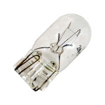
Eventually, even bulb changing didn’t suffice, and practically the whole system (six discrete fixtures) passed away. I started doing some research and discovered that instead of 120V, which I’d assumed from the original installation, the bulbs (with a wedge base, as shown at left) operated on a nominal 12V. I wound up opening one of the fixtures and discovered a small “power supply” therein. Further research indicated that several others had successfully replaced them with relatively inexpensive units and specified a retailer that purveyed them. I replaced all six.
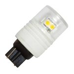
The repair was successful, but it was still xenon and still overly warm. Perusing the bulb section at the local home center, I discovered LED replacement bulbs with the same base configuration as the wedge base xenons. So, in dribs and drabs, I replaced all the xenon bulbs with the LED equivalents (they weren’ cheap—probably on the order of $15 each), and essentially, the lights came on in Florida. Let me give you an idea of the scale of the installation. There are six fixtures—one ≈7" long, two ≈13" long, two ≈22" long, and one ≈30" long. That’s respectively one bulb, two bulbs, three bulbs, and four bulbs—total fifteen. Doing the math tells you I had invested a fair amount in getting light on the counter. I won’t even admit to how much the installation originally cost—suffice to say I wasn’t interested in a wholesale fixture replacement.
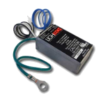
Sadly, over time, the LED bulbs began to fail, too. Initially, I replaced a couple of them with new, but I didn’t like the direction things were heading. I don’t know what epiphany I might have had, but the realization eventually come to me (probably from reading the specs on the power supplies) that maybe LEDs don’t care much for AC voltage. So, the first thought after that was to see if I could find a DC power supply in essentially the same form factor so they’d fit in the fixtures. Unfortunately (and I did this several times over a year or more), I had difficulty coming up with anything that remotely seemed like it would work. Eventually I decided to call upon an old ham radio buddy of mine, who actually does these kinds of things all the time.
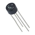
I flatter myself to think that he didn’t tell what exactly to do, but we sort of discussed that the LED bulbs probably didn’t much care for the AC supply. Somewhere the idea was floated about throwing a diode in line to rectify the voltage (yielding half wave, pulsing DC), but he thought it might be too much ripple and would be visible. I thought, “how about a full wave bridge rectifier?” (as at left), and he agreed. I wondered about throwing a capacitor in there to smooth out the pulses, with which he agreed and he suggested using an electrolytic. He also recommended a small current limiting resistor. I eventually abandoned the resistor as it dimmed the lights too much, and further reflection suggested the strips probably had current limiting built in. After all, the strips were designed to work with from 2" all the way to the full 1M on 12V, so it’s hard to imagine the manufacturer didn’t build it in.
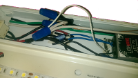
An awkward image depicting a fully modified fixture with power supply, rectifier, and wiring in one bay, and the LED strip in place in the other. The wiring bay is covered with a plain metal plate, while the lighting bay has a hinged glass cover.
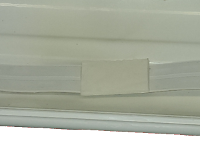
Just an orienting view to illustrate how I prepare the underside of the LED strip. This is double-sided tape and serves to affix the LED strip to the fixture (and the power supply/rectifier assemblies, as well). It also serves to insulate where copper tabs are located.

This is a before picture. This is the longest fixture (≈30") with four bulb bases attached. Please ignore the cluttered work area…
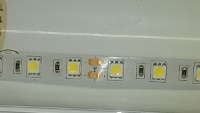
This image shows the LED strip double-side-taped to a fixture. The yellow tabs are the actual LED. I believe the little black things are current limiting resistors. The coppery tabs are solder points for the DC power and indicate at what point the strips can be cut to adjust for length. The strips come in a 1M length with copper tabs every two inches.
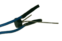
Here’s an image of the 12V AC lines (blue) from the power supply soldered to the AC inputs of the bridge rectifier, and then insulated with shrink tubing. The bare leads provided DC + and - which will have an electrolytic capacitor soldered across them. The leads will then be soldered to red and black wires, shrink tubing insulated, and which will run to the LED strips. Well, they worked, sort of. I had mixed results and some eventual failures. It was a disappointing result.
I’m not sure what the problem was. I’m a reasonably competent bread board electronics constructor, although seriously unpracticed for more than twenty years. What I thought I’d want, even at the start with the strips, was a dedicated 12V supply for each of the three pairs of fixtures. I was hoping to find something which would fit inside the fixtures, but space is really tight, and ultimately, I had to think outside the box…literally (or actually, I mean).
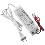
I found a likely solution (Armacost SLT30-12V), ordered one, and tried it out. Bingo, this was the answer to my problem, although I had to compromise a bit trying to comply with the NEC (National Electrical Code). It’s safe, but it might be a little hinky to an inspector. Thankfully, no inspector will ever see it in my lifetime.
One of the nice features about this unit is the flexibility in wiring options. The power cord you see is connected to screw terminals at the other end of the fixture which are just like the terminals to which the black and red wires are connected. I basically took black and white from the wall and connected directly to the terminals. The white cord was never used. Similarly, I ran black and red from inside the light fixture to the black and red terminals on the power supply. Both sets of terminals are covered.
The one-off experiment was a grand success, so I ordered the two more supplies I needed, and got them fully in place a few months ago (2016).
A couple of weeks later, it started to feel like deja vu, as both bride (Linda) and I noticed the one large bank by the fridge was much dimmer than it used to be. I flipped the hi-low switch and it reacted strangely and inconsistently. I thought about it for those two weeks, and then yesterday, with other projects at a break point and bride out of the house, I pulled the fixture down and apart, and took a look.
As soon as I got the switch disconnected from the two wire nut connections I could feel that one of the wires was extremely loose at the terminal. Surgery through the shrink tubing exposed all, and the wire actually fell away in my hand. Thus the intermittentcy.
The fix couldn’t have been easier. I fired up the soldering iron, cut a new piece of shrink tubing, melted the solder on the tab and pushed the wire through. I didn’t even need to trim it off. I pushed the shrink tubing down onto the terminal, shrunk it, then tested the fixture. Bingo!
Reassembly, left it burning all day, bride noticed it when she got home, and after weeks of worrying I had another one of those slow developing failures in our under cabinet lighting, we’re back in play 100%. Yay!
Last updated: 30 November 2017