A neighbor was doing a vast remodel on her house in the neighborhood. She showed me a project that had her, if not stumped, at least puzzled. An antique four poster bed that she had obtained only had three finials for four posts. I noticed as we were leaving that she had these two other finials on a shelf in the garage. I suggested, “why not use those at one end of the bed? No, they don’t match the others, but so long as you have pairs, very few will catch the differences from head to foot.”
The bed is massive, anyway, and the room is cozy, so it will be hard for anyone to take in the full scope of the bed to notice the difference in finials. So, guess who volunteered to cut them down? I had just cut a column for the bar top in her kitchen, so I guess trimming of large objects was now part of my toolkit. I love a challenge, though.
Incidentally, I subsequently learned that calling these pieces “finials” isn’t quite accurate. They were originally legs to a coffee table and not bed parts at all. As you will see, there was a happy accident in the finish of them, as well. Now they can be called finials.
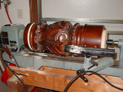
I didn’t grab a true “before” image of the finials as I got them from the neighbor, but here’s one all chucked up in the lathe and the only difference is the groove already cut at the left and (top of the finial) and that I’d already fashioned the plugs and drive caps for mounting on the lathe. Let’s go from there.
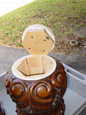
Here’s a detail of one of the end caps, featuring the hex plug I had crafted to fit inside the segmented finial. The plug ensured consistent alignment of the work as well as providing purchase for the lathe centers to drive it. The plugs will be repurposed as permanent inserts for the finials after they’re installed.
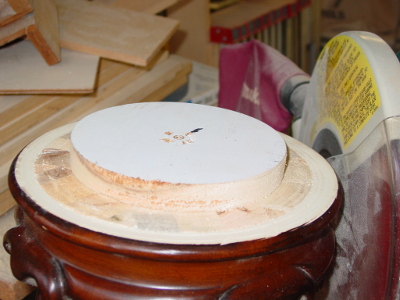
This is what a cap/plug assembly looks like on the end of the finial. Because I wasn’t so rigorous about taking pictures as I went along, this is actually after the top of this one has been parted off.
For those unfamiliar with turning, separating a turning from the waste is called “parting”, and is done with a, wait for it, parting tool. It’s basically a thin tool that you press into the work and it removes wood leaving a kerf the width of the tool. In actual use, particularly for a deep cut, as this is, a “relief cut” is made, which is basically just using the tool adjacent to a portion of the previous cut to double or triple its width, thus preventing excessive friction as the tool goes deeper into the wood.
Another function of the parting process is to “dress” the cut to result in either a concave or convex form in the finish cut. If concave, this results in a wobble free finished project with the outer dimension fully in contact with the mating surface all the way around.
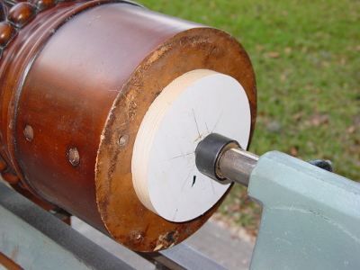
This is the work chucked up with the cap/plug in place as in the above description. This is the bottom of the original finial, and the tail stock with a “live” center holds it in place.
It’s complicated to explain, but regardless of careful measuring and layout, it is impossible to chuck up a piece of round work like this, perfectly centered. Fortunately, I was able to get it almost centered on the bottom, and reasonably so on the top. Perfect centering isn’t as important for the parting cut, as eventually you fully contact the work with the tool and the “finish surface” is buried in the work and will never be visible. In fact, by definition, if parting off a hollow piece, such as this, the end of the cut will wind up in air, so a requirement for true centering becomes moot.
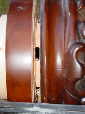
This is how you tell you’ve gone deep enough with the parting tool. That black rectangle (and the other black spots) are air—they represent the joint between two segments and the resulting “V” profile on the inside of the finial. The wood left is across the flats, and represent plenty of support remaining. But, this is deep enough.
With the lathe stopped, I got out my trusty dozuki (Japanese pull saw—very flexible, very thin kerf) and proceeded to make more air. It took just a few pulls and repeated manual rotation of the workpiece and they were disconnected. I withdrew the tailstock and unmounted the finial.

I’ve pulled the cap/plug from the cutoff and remounted it on the new top of the finial. You can see the marks made by the teeth on the spur drive in the headstock spindle. Also you can see a Sharpie™ mark. It’s wise practice to have some sort of indexing mark on your drive spur and then mark your work adjacent to it. If you ever have to remount a workpiece, you’ll be more likely to get a nice concentric mount if you do that. Notice I said “more likely”. It’s not assured, but your chances are better.
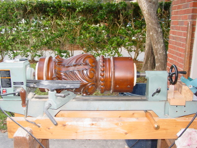
To, ahem, recap—this is what the original finial looked like mounted to the lathe. The first parting cut has been made at the top (left) of the finial.
Not plain in the picture, and probably not considered by one unacquainted with turning, is the fact that the “banjo”—the tool rest support casting that clamps to the ways (bed) of the lathe—fit nicely in the concave curve of the carving. It’s the only place on the work piece that would clear the banjo.
When it came time to part off the bottom, I had to place the banjo completely to the right of the work, at an angle, and work off the far left of the tool rest. Fortunately, the castings are strong and the workpiece was very well balanced and concentric at the right end of the lathe, consequently, hardly any tool bounce, and a clean cut.
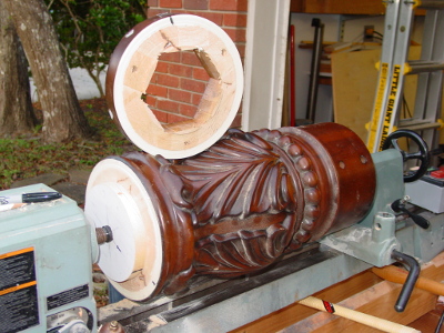
Here’s the result after cutting off the top, re-seating the cap/plug, and remounting the work. Note the banjo is holding up the bottom of the finial, in anticipation of moving the tail stock, extending the spindle, and positioning the banjo/tool rest.
The parting off of the bottom is identical to the parting off of the top, including the dozuki work.
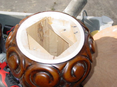
Once I cleaned up the base of each finial I glued and screwed a couple of support pieces as seen here. They’re designed to support the bottom plug which will be reinstalled on each one. Double duty—pretty cool, eh?
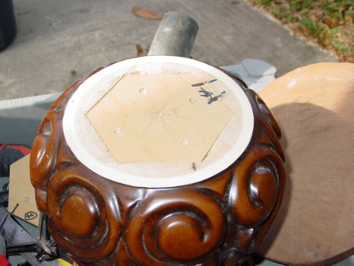
Here’s the plug in place (although, as yet, unfastened). I’ll drill roughly a ¾" hole in the center for a pin that will slip into an existing nut on top of each post. The original finial had a plate with a ¾"-10 bolt attached, and the finial then screwed into the nut. Given the height and weight of the finial (within a couple of inches of the ceiling) the threaded attachment is serious overkill. It would take an energetic eightsome in their twenties on this twin-sized bed to dislodge either assembly.
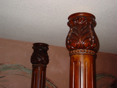
The finials mounted to the top of the posts. There is no way in the world anyone could have anticipated not only the fit of the disparate parts, but that the finish would so perfectly match, particularly coming from two entirely unrelated pieces of furniture—both in purpose and provenance.
With the finials completed and installed, it was time to attack the frame rails. The original bed had been a king size and the neighbor had cut the head and foot boards down to fit a twin which was all she needed for the room. But the rails also needed to be shortened from 82" to 75".
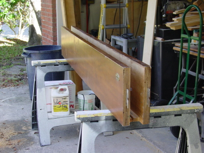
Here they sit, ready to be attacked. They are quite massive pieces compared to the usual adjustable steel frame.
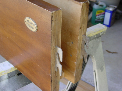
This is the tricky part. These steel plates are mounted in slots in the end of the rail, and secured by ≈¼" steel pins. You can see the ends of the pins on the rear piece. All they are is a friction fit in the hole, but they securely lock the plates in place, and the protruding hooks attach to slots on corresponding plates mounted in the posts.
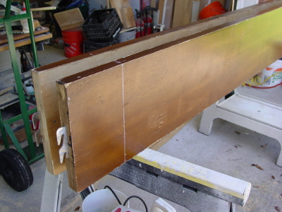
The chalk line is the location of the separating cut to be made.
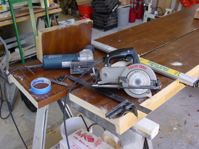
Parts cut. These are the tools used. The circular saw didn’t quite have enough depth of cut to separate the pieces, so I made a second pass with the jig saw. I was amazed to learn (after owning these tools for many years) that the distance from blade to the right edge of the bottom plate of each saw was identical. That meant I didn’t have to move the clamp (long silver thing at the back of the collection) when I made the cleaning cut. The blue tape was used to reduce splintering in the finish veneer.
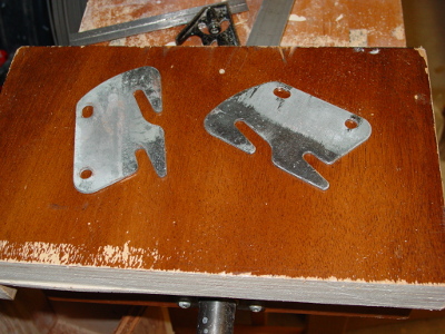
These are the plates after they were removed from the off cuts. Engaging details of the process of removing the pins (in blind holes) and prying out the plates aren’t really necessary to relate and reside happily in the mind of the DIYer.
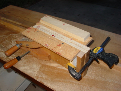
When it came time to cut the slots for the plates, some precision and repeatability was needed. Precision because the plates are just a bit thicker than the kerf left by my saw. Repeatability, because I had to do it twice on pieces of mirror image profile. So I built a fixture.
It’s impossible to tell from this image, but the top most blonde piece of wood is a fence, adjustable to two positions, permitting me to make two passes with the saw, thus increasing the kerf width.
Also impossible to tell, but worth noting, is the reddish stains on the fixture. Yes, that is my blood. I had a bit of a screw driving accident. Who knew a #2 Philips bit would be so sharp?
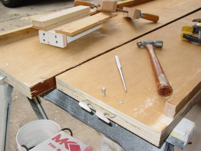
Plates installed. I wound up having to use my 6" SawBoss instead of my 4¼" Trim Saw because I needed just a touch more depth of cut. Who says size doesn’t matter?
One of the pins that holds the plate in place is left standing proud for the picture, but was fully seated to complete the installation. The alignment tool (silver thingy) helped position the plate and the hammer did the hammering. Also seen is the fixture and clamps used to make the cuts. Since three hands were required to maneuver the saw, I couldn’t get a picture of the actual slot cutting.
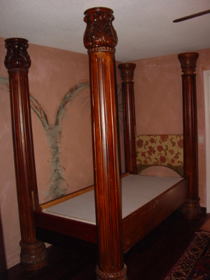
And, the final result, sans mattress (bolts through the head and foot boards still need to be installed). A really nice result, to my mind.
Looking back at this a few years later, I can’t help but wonder how much easier, yet possibly not so demanding of creative thinking, this would have been if I’d had my new Nova Galaxi lathe.
Last updated: 15 August 2018